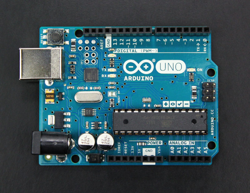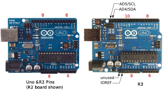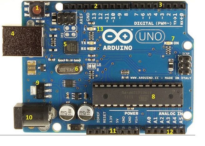


Instead, it features the Atmega16U2 (Atmega8U2 up to version R2) programmed as a USB-to-serial converter. The Uno differs from all previous boards in that it does not use the FTDI USB-to-serial driver chip. It contains everything needed to support the microcontroller simply connect it to a computer with a USB cable or power it with an AC-to-DC adapter or battery to get started. It has 14 digital input / output pins (of which 6 can be used as PWM outputs), 6 analog inputs, a 16 MHz ceramic resonator, a USB connection, a power jack, an ICSP header, and a reset button. Just connect the DC source at analog in A0 to measure the DC voltage.The Arduino Uno is a microcontroller board based on the ATmega328 (datasheet). This code will help you to convert this board into a 0 to 5V Voltmeter. How to burn the bootloader in an Arduino Nano using an Arduino UNO – Īrduino example code is provided below to test the project.From Arduino to a Microcontroller on a Breadboard –.Refer to the connection diagram and follow the links below to learn more about bootloader and Arduino IDE programming. On-Board Arduino IDE Programming Connector (RX, TX, Reset, VCC and GND Pins)Īfter the board assembly, the brand new Atmega328 microcontroller requires burning the bootloader before it can be programmed using Arduino IDE.On-Board Bootloader Burning Connector for New ATmega328 Micro-controller (D10, D11, D12, D13, VCC and GND Pins).On-Board Current Limiting Resistor R2/R3 for LCD Back Light.


The operating power supply is 7 to 15V DC. The Arduino Uno and Arduino Uno revision 2 both have a LED and resistor connected in series on Arduino pin 13. The board enables the easy interface of many devices and sensors. Each Arduino I/O Pin including the VCC and GND is exposed to the connectors for easy connection with sensors and other devices. The Arduino compatible hardware includes onboard programming and boot-loader connectors, Atmega328 microcontroller, and 16×2 LCD interface. This is a low-cost solution that has onboard Arduino + LCD so no extra Arduino Nano or Arduino board is required. The board has the exact size of 16×2 LCD and can be installed on the backside of the LCD. The LCDduino board enables users to create many applications/projects that require a 16×2 LCD display and Arduino.


 0 kommentar(er)
